

I just recently pulled the trigger on purchasing some Halos for my Sling and wanted to be able to run them without my headlights. After researching some of the Headlight Bypass Kits available, I didn't want to spend the asking price for a bypass switch and I wasn't thrilled about the methods of install. Some kits want you to drill a hole through the fuse box cover. The fuse box cover has a gasket seal around it to prevent dust and moisture from getting in there and I didn't want to compromise that. Here is my attempt to show/explain what I did.
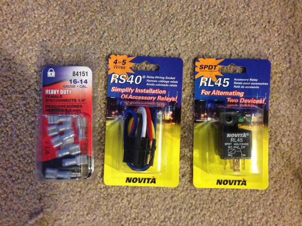
*Noteworthy mention - I did have to cut a factory wire going to the fuse box, but I think it made for a cleaner install and was worth it. If that worries you, you probably shouldn't attempt this mod. All in all, this mod cost me around $10. I had to purchase a relay wiring socket, a relay and a package of 1/4" female disconnects.
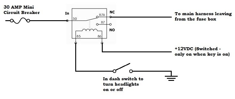
To give you an idea of what we are trying to accomplish before we dive into it, here is a rough schematic of what we are going to do:
I won't bore those who just want to get on with it, but if you have any questions, concerns or comments I'd love to hear them, as this is my first 'How-To' guide. If you attempt this, you do so at your own risk!! I am simply providing this for informational purposes on what I did to mod my Sling.
Needed tools and materials:
- 10mm socket and ratchet
- T30 Torx screwdriver
- M5 Allen wrench
- Wire cutters
- Wire strippers
- Jewelers flat tip screwdriver (or similar long thin tool)
- Various sizes of small heat shrink
- Heat gun (or blow-dryer will work)
- solder
- soldering iron
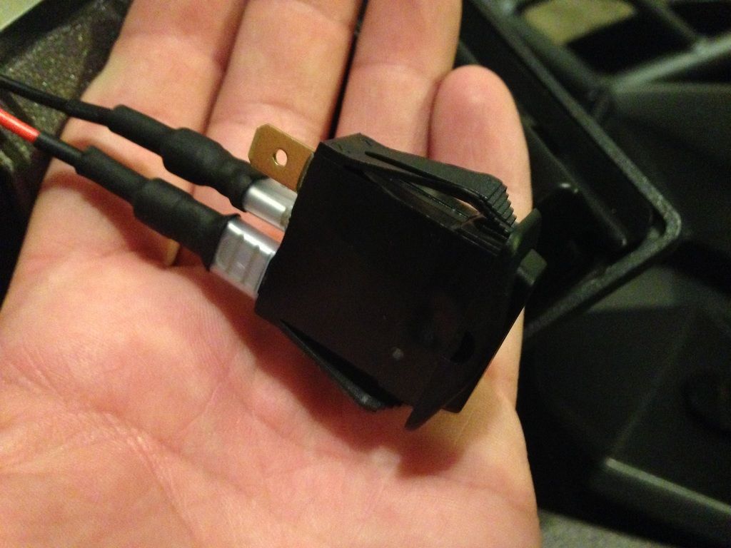
- rocker or toggle switch
- approximately 12' of 14 gauge stranded wire
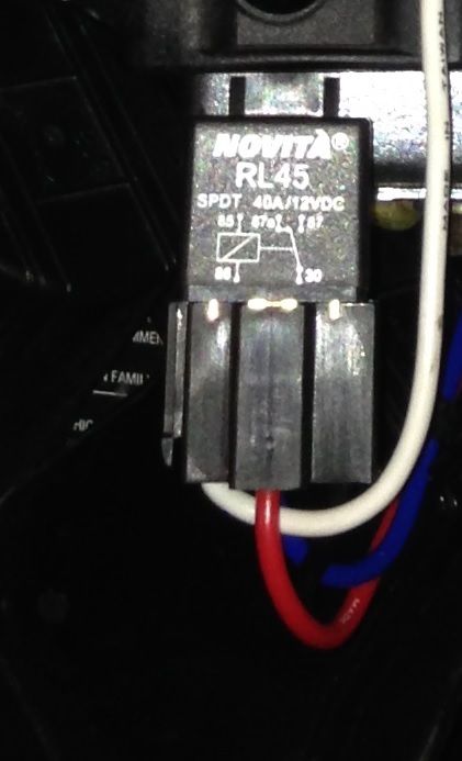
- 12VDC 40AMP SPDT Automotive relay
- Relay socket
- Female quick disconnects
paslinger[/user] suggestion - Disconnect the battery prior to beginning Step 1. (I 100% agree, I was just being lazy when I did it, but this is undoubtedly the more intelligent route!)
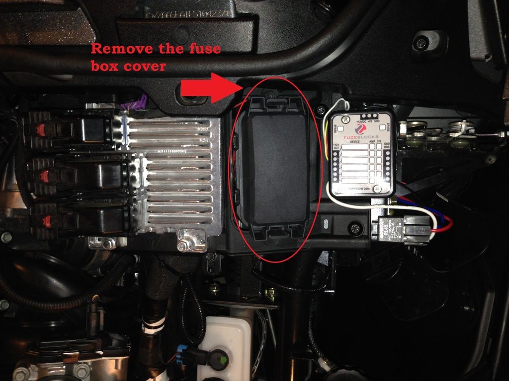
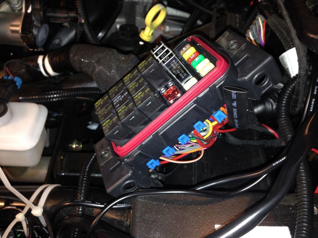
1. Remove the fuse box cover.
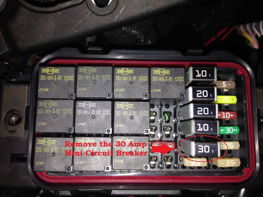
2. Remove the 30 Amp Mini-Circuit Breaker.
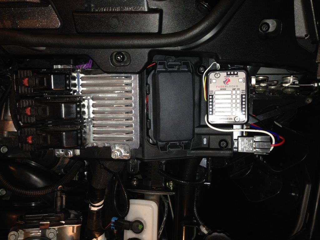
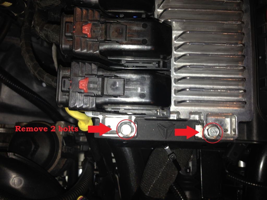
3. Remove the 2 10mm bolts and slide the ECU toward the front of the vehicle to move it out of the way.
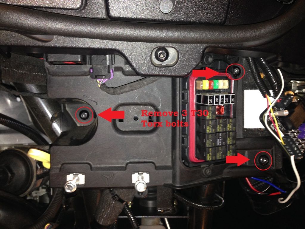
4. Remove 3 T30 Torx bolts.
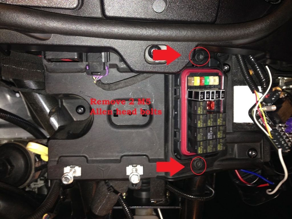
5. Remove 2 M5 Allen head bolts.
6. Carefully lift the ECU/Fuse Box mount to the side and out of the way. (not the fuse box itself, but the mount that it sits in)
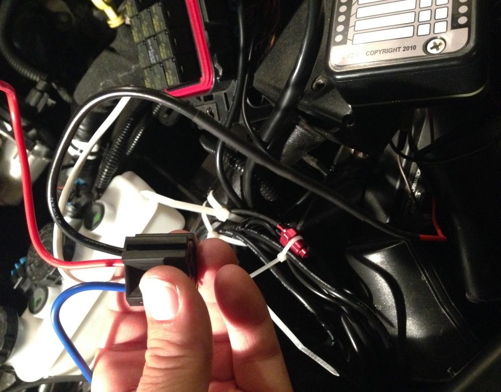
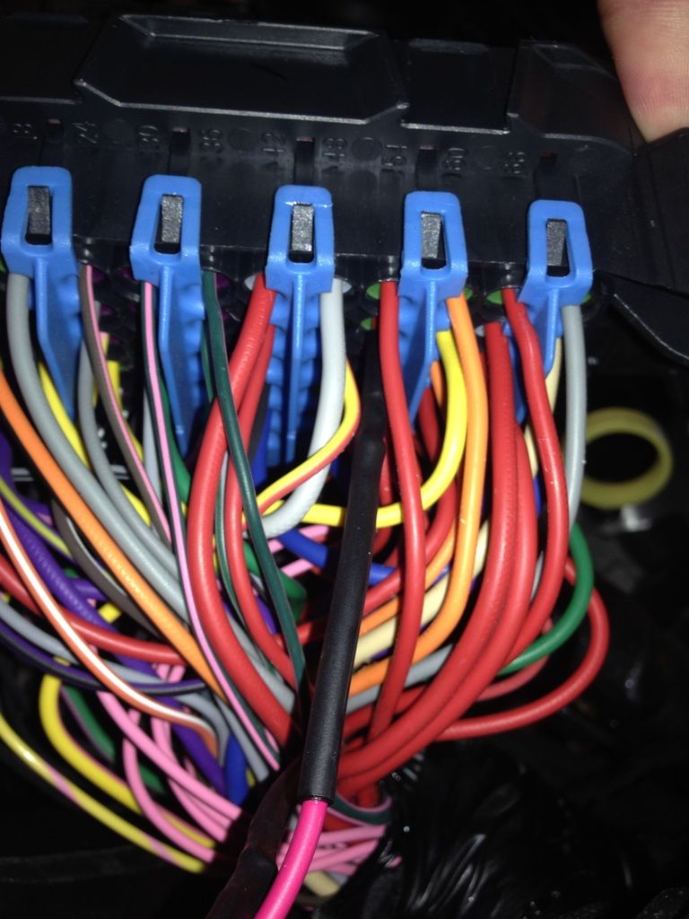
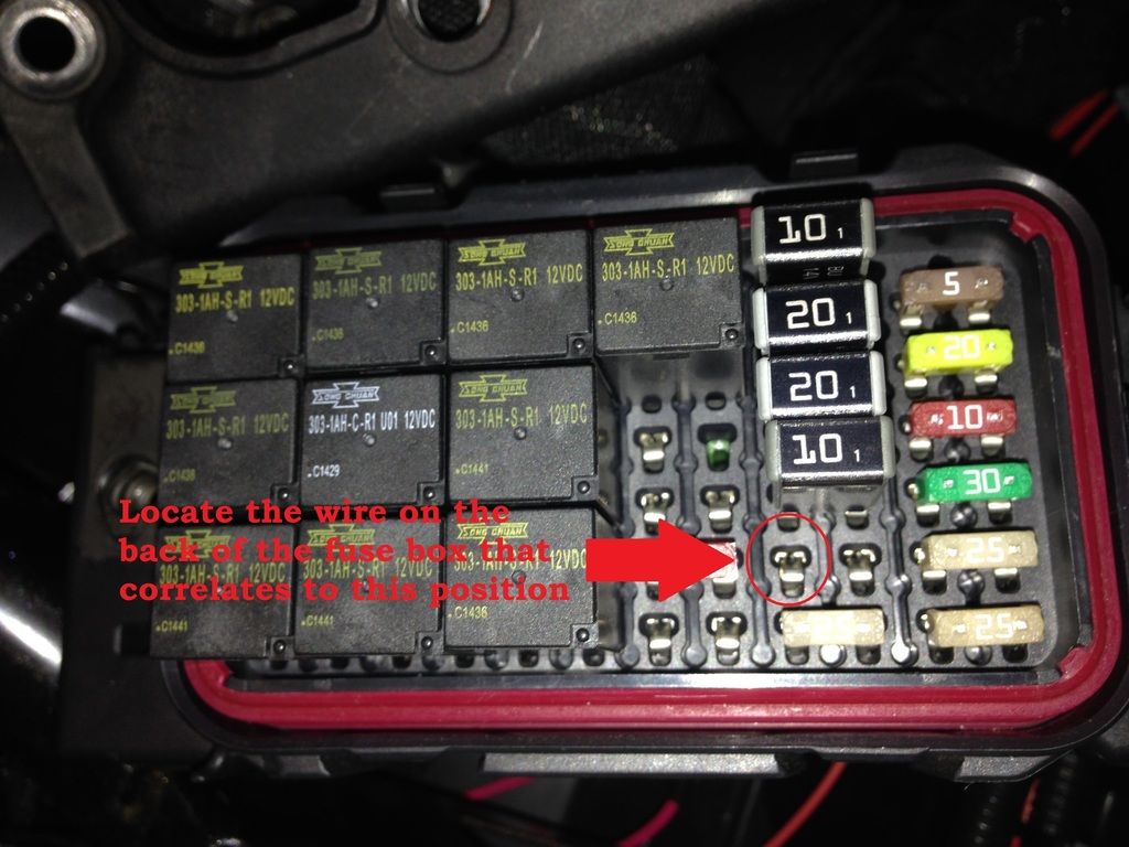
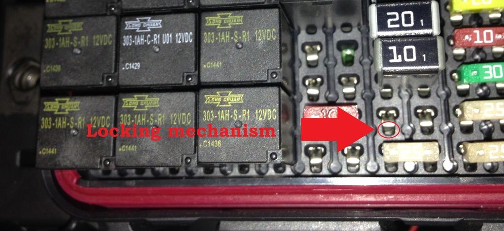
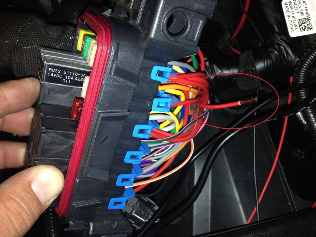
7. Locate the wire red wire on the bottom of the fuse box that corresponds with the left leg of the 30 Amp Mini-Circuit breaker as indicated in the picture below. There is a blue clip on the bottom of the fuse box that helps guide and lock the wires in. Carefully unclip and slide down just a bit, but there is no need to fully remove it.
8. Use a long slender tool to release the locking mechanism which holds the female plug in place. A long thin scribe or jewelers screwdriver should do the trick.
*If you were smart and disconnected the battery this won't be an issue, if you were like me and skipped that step the use CAUTION when doing this, as +12VDC is present. Do not allow your tool or the connector to come into contact with a ground, such as the chassis of the Slingshot.
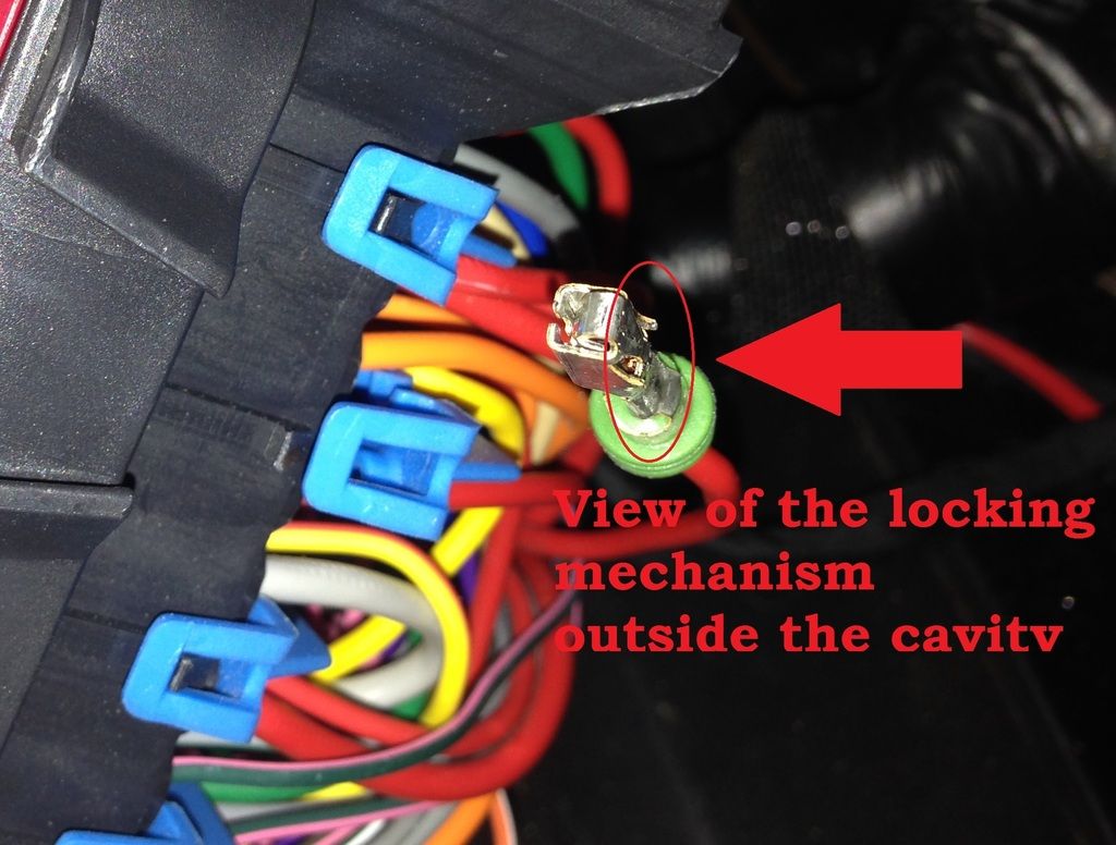
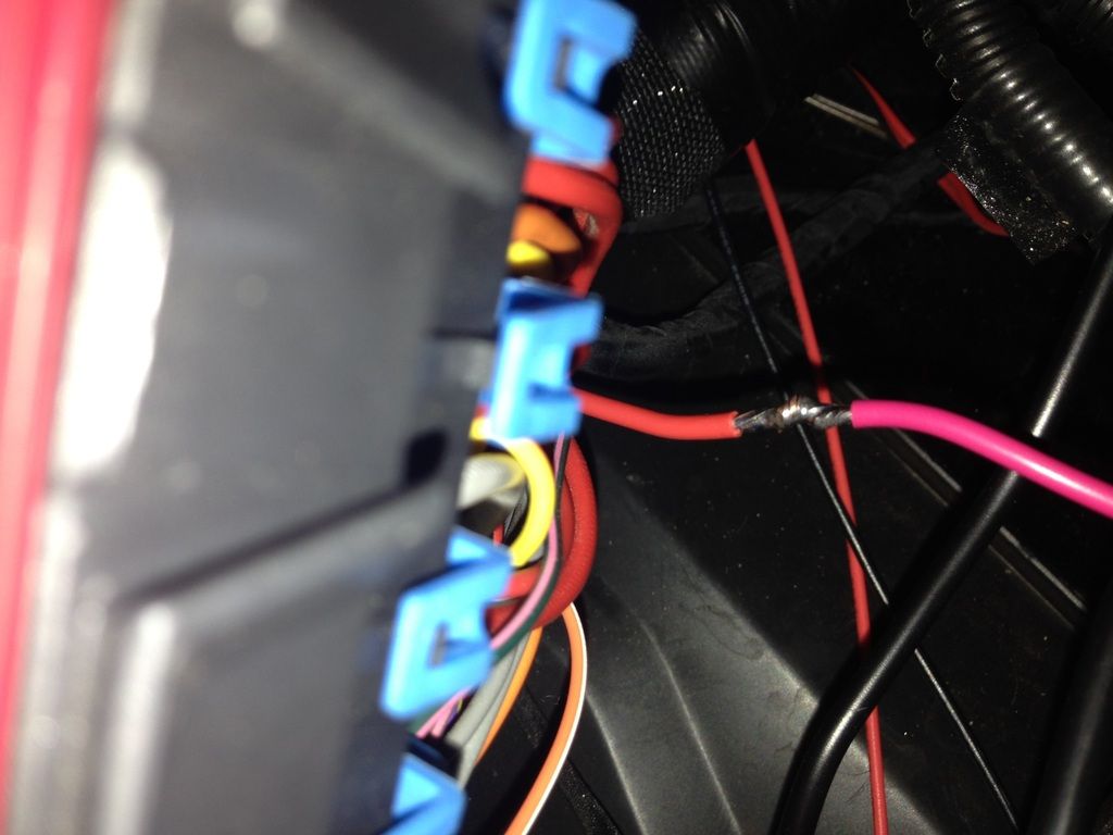
I placed a piece of heat shrink on the connector to prevent it from shorting to ground while I was working.
10. Now this is the point of no return, here we will need to cut the wire we just pulled from the fuse box. You will need to be able to work with both ends, but there isn't a whole lot of wiggle room. Cut the wire so that you have just enough length on both ends to work with. Also, remember, this end is still hot, so DO NOT let it touch anything metal.
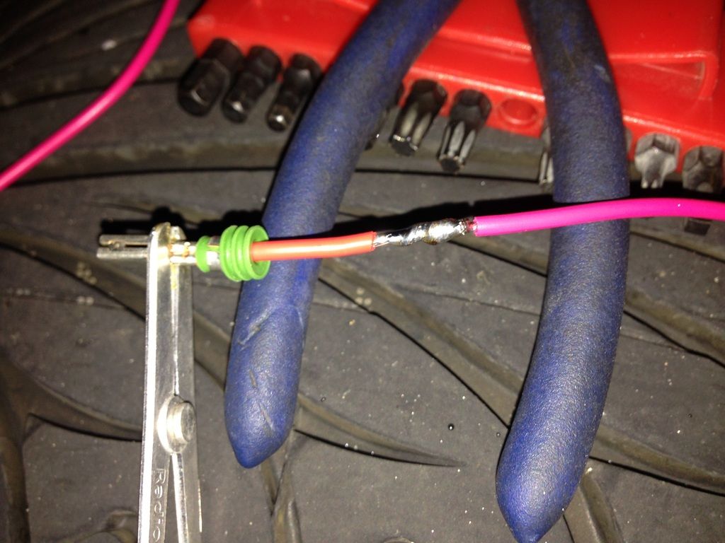
11. Solder a length of 14 gauge (size) stranded wire to this end and cover with heat shrink.
***Using wire of at least equal gauge of the stock wiring is important. Failure to do so, could cause a fire!!!
12. Now solder this wire to the lead of your relay socket that corresponds to the 30 contact of the relay. (For me this was a Blue wire) Again, don't forget to put your heat shrink on before you make the connection.
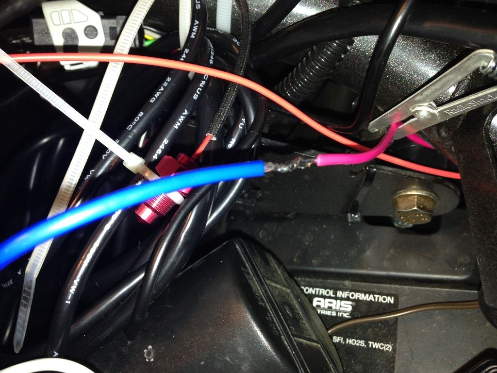
13. Now solder a length of 14 gauge wire to the other end of the wire you cut off in Step 10.
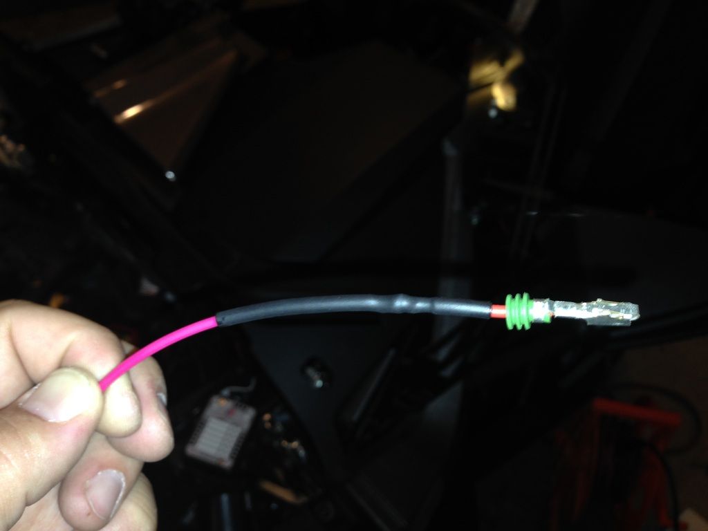
14. Now solder this wire to the lead of your relay socket that corresponds to the 87A contact of the relay. (For me this was a Red wire) Again, don't forget to put your heat shrink on before you make the connection.
It's important to use 87A and not 87. If you use 87 and the relay fails, you will be stuck without headlights until you can replace the relay. As long as you use 87A, if the relay fails, you will just be unable to turn your headlights off until you replace the relay.
*Note - this wire is no longer hot, as long as the relay is not in the relay socket.
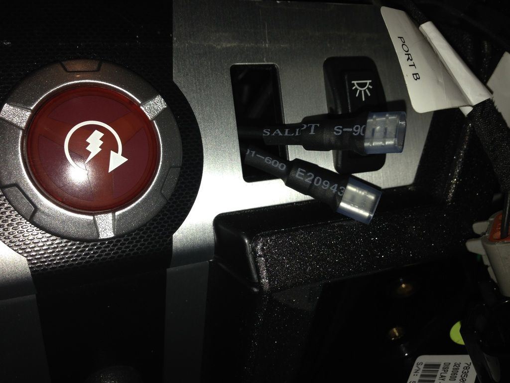
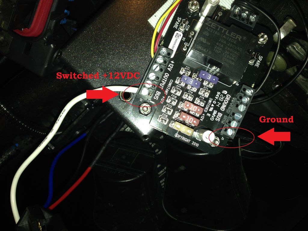
15. Run 2 lengths of wire from the desired mounting location of the relay (probably very near to the fuse box) to the desired mounting location of the rocker or toggle switch you will use to turn the headlights on and off. I used a stock switch in the stock location under the cubby hole or radio. I crimped 1/4" female disconnects on the ends of my wires to connect to my switch.